图书介绍
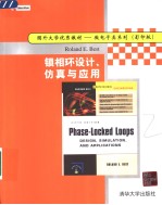
锁相环设计仿真与应用 影印版PDF|Epub|txt|kindle电子书版本网盘下载

- 贝斯特著 著
- 出版社: 清华大学出版社
- ISBN:7302077299
- 出版时间:2003
- 标注页数:421页
- 文件大小:104MB
- 文件页数:40038883页
- 主题词:
PDF下载
下载说明
锁相环设计仿真与应用 影印版PDF格式电子书版下载
下载的文件为RAR压缩包。需要使用解压软件进行解压得到PDF格式图书。建议使用BT下载工具Free Download Manager进行下载,简称FDM(免费,没有广告,支持多平台)。本站资源全部打包为BT种子。所以需要使用专业的BT下载软件进行下载。如BitComet qBittorrent uTorrent等BT下载工具。迅雷目前由于本站不是热门资源。不推荐使用!后期资源热门了。安装了迅雷也可以迅雷进行下载!
(文件页数 要大于 标注页数,上中下等多册电子书除外)
注意:本站所有压缩包均有解压码: 点击下载压缩包解压工具
图书目录
Chapter 1. Introduction to PLLs1
1.1 Operating Priciples of the PLL1
1.2 Classification of PLL Types5
Chapter 2. Mixed-Signal PLLs7
2.1 Block Diagram of the Mixed-Signal PLL7
2.2 A Note on Phase Signals8
2.3 Building Blocks of Mixed-Signal PLLs11
2.3.1 Phase Detectors11
2.3.2 Loop Filters (First Order)23
2.3.3 Controlled Oscillators26
2.3.4 Down-Scalers29
2.4 PLL Performance in the Locked State29
2.4.1 Mathematical Model for the Locked State30
2.4.2 Definition of Transfer Functions31
2.4.3 Transient Response of the PLL in the Locked State36
2.4.4 Steady-State Error of the PLL39
2.5 The Order of the PLL System41
2.5.1 Number of Poles41
2.5.2 A Special Case: The First-Order PLL42
2.6 PLL Performance in the Unlocked State42
2.6.1 Mathematical Model for the Unlocked State42
2.6.2 Key Parameters of the PLL51
2.7 Phase Detectors with Charge Pump Output73
2.8 PLL Performance in the Presence of Noise80
2.8.1 Sources and Types of Noise in a PLL80
2.8.2 Defining Noise Parameters82
2.8.3 The Impact of Noise on PLL Performance83
2.8.4 Pull-in Techniques for Noisy Signals91
2.9 Design Procedure for Mixed-Signal PLLs93
2.10 Mixed-Signal PLL Applications102
2.10.1 Retiming and Clock Signal Recovery102
2.10.2 Motor-Speed Control109
Chapter 3. PLL Frequency Synthesizers115
3.1 Synthesizers in Wireless and RF Applications115
3.2 PLL Synthesizer Fundamentals116
3.2.1 Integer-N Frequency Synthesizers116
3.2.2 Case Study: Designing an Integer-N PLL Frequency Synthesizer123
3.2.3 Fractional-N Frequency Synthesizers127
3.3 Single-Loop and Multiloop Frequency Synthesizers132
3.4 Noise in Frequency Synthesizers134
3.4.1 Phase Jitter??n,ref of the Reference Oscillator136
3.4.2 Phase Jitter??n,vco of the VCO144
3.4.3 Reference Feedthrough Created by the Phase Detector145
Chapter 4. Higher-Order Loops151
4.1 Motivation for Higher-Order Loops151
4.2 Analyzing Stability of Higher-Order Loops151
4.3 Designing Third-Order PLLs155
4.3.1 Passive Lead-Lag Loop Filter155
4.3.2 Active Lead-Lag Loop Filter157
4.3.3 Active PI Loop Filter159
4.4 Designing Fourth-Order PLLs162
4.4.1 Active Lead-Lag Loop Filter162
4.4.2 Active PI Loop Filter165
4.5 Designing Fifth-Order PLLs168
4.5.1 Active Lead-Lag Loop Filter168
4.5.2 Active PI Loop Filter172
4.6 The Key Parameters of Higher-Order PLLs176
4.7 Loop Filters for Phase Detectors with Charge Pump Output177
4.7.1 Loop Filters for Second-Order PLLs177
4.7.2 Loop Filters for Third-Order PLLs178
4.7.3 Loop Filters for Fourth-Order PLLs179
4.7.4 Loop Filters for Fifth-Order PLLs180
Chapter 5. Computer-Aided Design and Simulation of Mixed-Signal PLLs181
5.1 Overview181
5.2 Quick Tour182
5.2.1 Configuring the PLL System182
5.2.2 Designing the Loop Filter184
5.2.3 Analyzing Stability of the Loop186
5.2.4 Getting the Loop Filter Schematic188
5.2.5 Running Simulations190
5.2.6 Getting Help193
5.2.7 Shaping the Appearance of Graphic Objects193
5.3 Case study: Design and Simulation of a Second-Order PLL194
5.4 Suggestions for Other Case Studies201
5.5 Displaying Waveforms of Tristate Signals202
Chapter 6. All-Digital PLLs (ADPLLs)205
6.1 ADPLL Components205
6.1.1 All-Digital Phase Detectors205
6.1.2 All-Digital Loop Filters211
6.1.3 Digital-Controlled Oscillators216
6.2 Examples of Implemented ADPLLs221
6.2.1 ADPLL Example 1221
6.2.2 ADPLL Example 2225
6.2.3 ADPLL Example 3227
6.3 Theory of a Selected Type of ADPLL228
6.3.1 Effects of Discrete-Time Operation228
6.3.2 The Hold Range of the ADPLL234
6.3.3 Frequency-Domain Analysis of the ADPLL237
6.3.4 Ripple Reduction Techniques239
6.3.5 Higher-Order ADPLLs240
6.4 Typical ADPLL Applications241
6.5 Designing an ADPLL243
6.5.1 Case Study: Designing an ADPLL FSK Decoder243
Chapter 7. Computer-Aided Design and Simulation of ADPLLs247
7.1 Setting up the Design Parameters247
7.2 Simulating ADPLL Performance249
7.3 Case Studies of ADPLL Behavior250
Chapter 8. The Software PLL (SPLL)257
8.1 The Hardware-Software Tradeoff257
8.2 Feasibility of an SPLL Design258
8.3 SPLL Examples259
8.3.1 An LPLL-like SPLL260
8.3.2 A DPLL-like SPLL266
8.3.3 A Note on ADPLL-like SPLLs275
Chapter 9. The PLL in Communications277
9.1 Types of Communications277
9.1.1 From Analog to Digital277
9.2 Digital Communications by Bandpass Modulation279
9.2.1 Amplitude Shift Keying279
9.2.2 Phase Shift Keying280
9.2.3 Quadrature Phase Shift Keying281
9.2.4 QAM (m-ary Phase Shift Keying)282
9.2.5 Frequency Shift Keying284
9.3 The Role of Synchronization in Digital Communications285
9.4 Digital Communications Using BPSK286
9.4.1 Transmitter Considerations286
9.4.2 Receiver Considerations291
9.5 Digital Communications Using QPSK301
9.5.1 Transmitter Considerations301
9.5.2 Receiver Considerations303
9.6 Digital Communications Using QAM306
9.7 Digital Communications Using FSK307
9.7.1 Simple FSK Decoders: Easy to Implement, but Not Effective307
9.7.2 Coherent FSK Detection308
9.7.3 Noncoherent FSK Detection and Quadrature FSK Decoders310
Chapter 10. State of the Art of Commercial PLL Integrated Circuits311
Chapter 11. Measuring PLL Parameters327
11.1 Measurement of Center Frequency fo327
11.2 Measurement of VCO Gain Ko328
11.3 Measurement of Phase-Detector Gain Kd329
11.4 Measurement of Hold Range??h and Pull-in Range??331
11.5 Measurement of Natural Frequency?? Damping Factor??, and Lock Range??334
11.6 Measurement of the Phase-Transfer Function H(??) and the 3-dB Bandwidth??3dB337
Appendix A. The Pull-in Process341
A.1 Simplified Model for the Pull-in Range?? of the LPLL341
A.2 Simplified Model for the Pull-in Time TP of the LPLL348
A.3 The Pull-in Range?? of the DPLL352
A.4 The Pull-in Time TP of the DPLL353
Appendix B. The Laplace Transform355
B.1 Transforms Are the Engineer's Tools355
B.2 A Laplace Transform Is the Key to Success359
B.3 A Numerical Example of the Laplace Transform362
B.4 Some Basic Properties of the Laplace Transform363
B.4.1 Addition Theorem363
B.4.2 Multiplication by a Constant Factor k363
B.4.3 Multiplication of Signals363
B.4.4 Delay in the Time Domain367
B.4.5 Differentiation and Integration in the Time Domain368
B.4.6 The initial- and Final-Value Theorems371
B.5 Using the Table of Laplace Transforms372
B.6 Applying the Laplace Transform to Electric Networks373
B.7 Closing the Gap between the Time Domain and the Complex-Frequency Domain376
B.8 Networks with Nonzero Stored Energy at t = 0377
B.9 Analyzing Dynamic Performance by the Pole-Zero Plot379
B.10 A Simple Physical Interpretation of "Complex Frequency"382
Appendix C. Digital Filter Basics385
C.1 The Transfer Function H(z) of Digital Filters385
C.2 IIR Filters388
C.2.1 The Impulse-Invariant z Transform388
C.2.2 The Bilinear z Transform395
C.3 FIR Filters399
C.3.1 Window-FIR Filters404
C.3.2 Designing FIR filters with the Parks-McClellan Algorithm408
References415
Index417